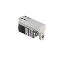
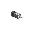
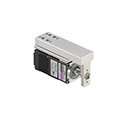
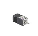
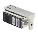
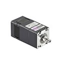
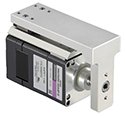
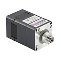
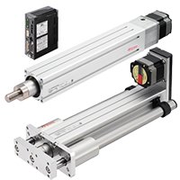
DRL II Series Compact Linear Actuators
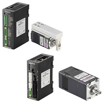
DRL II Series Compact Motorized Cylinders - Stepper Motors with Linear Ball Screw
High-precision integrated ball screw incorporated into a stepper motor for continuous high-positioning linear motion.
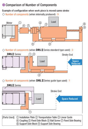
Available with or without guide, adjustment knob or electromagnetic brake. Reduces the number of components such as couplings and secondary external guides to make equipment more compact, quicker to install with less parts to order.
Built-in Controller (Stored Data) allows for easy networking and simplified multi-axis control.
- Standard (0.72°) or High-Resolution (0.36°) Motor Types
- Built-in Controller (Network Type) or Pulse Input Type Drivers
- 24 VDC Input
- Repetitive Positioning Accuracy
- Ground Ball Screw = ±0.003 mm
- Rolled Ball Screw = ±0.01 mm
Linear Actuator Lineup
Actuator Type |
Driver Type |
Power Supply |
Available Options |
Thrust Force |
Stroke |
||
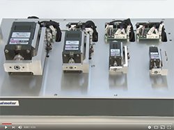
20 mm (0.79 in.) Linear Actuator with Guide |
24 VDC |
Adjustment Knob |
15 N |
3.3 lb |
25 mm |
0.98 in. |
|
20 mm (0.79 in.) Linear Actuator |
24 VDC |
Adjustment Knob |
15 N |
3.3 lb |
25 mm |
0.98 in. |
|
28 mm (1.10 in.) Linear Actuator with Guide |
24 VDC |
Adjustment Knob |
30 N |
6.7 lb |
30 mm |
1.18 in. |
|
28 mm (1.10 in.) Linear Actuator |
24 VDC |
Adjustment Knob |
30 N |
6.7 lb |
30 mm |
1.18 in. |
|
42 mm (1.65 in.) Linear Actuator with Guide |
24 VDC |
Adjustment Knob Electromagnetic Brake |
30 N 100 N |
6.74 lb 22 lb |
40 mm |
1.57 in. |
|
42 mm (1.65 in.) Linear Actuator |
24 VDC |
Adjustment Knob Electromagnetic Brake |
30 N 100 N |
6.74 lb 22 lb |
40 mm |
1.57 in. |
|
60 mm (2.36 in.) Linear Actuator with Guide |
24 VDC |
Adjustment Knob Electromagnetic Brake |
300 N |
67 lb |
50 mm |
1.97 in. |
|
60 mm (2.36 in.) Linear Actuator |
24 VDC |
Adjustment Knob Electromagnetic Brake |
300 N |
67 lb |
50 mm |
1.97 in. |
|
Compact Motorized Cylinders
Reliable Design and Structure
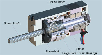
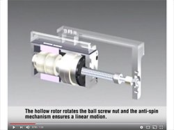
The DRLII Series features a structure in which the rotor is hollowed out and the ball screw is stored inside. The rotation of the hollow rotor rotates the ball screw nut and by setting up an anti-spin mechanism* on the tip of the ball screw, the ball screw shaft is moved in a linear manner.
Because the ball screw shaft is stored in the hollow rotor section, the maximum stroke is secured with the shortest overall length. Also, a large bore bearing is positioned on the outer circumference of the ball screw nut in order to directly receive the large thrust loads generated in linear motion.
*Not necessary for the guide type.
High Positioning Accuracy
The ball screw nut is linked with the hollow rotor. Through the coupling rigidity and other aspects of parts combination, the impact of backlash has been minimized achieving high-precision positioning.

Significantly Reduced Time Required for Design
The compact body houses the entire linear-motion mechanism. The use of conventional internally-produce parts is no longer required, thus reducing the time for equipment design and parts selection. Moreover, this reduces the time required for assembly and increases your production efficiency.
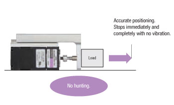
Stops Immediately Without Vibration
The DRLII Series compact linear actuators use stepper motors. Because this is a stepper motor, the positioning precision per step is high and the motor can be moved forward and back accurately.
Also, since the fine movement of the shaft (called hunting) does not occur when stopping, the stop position can be held correctly.
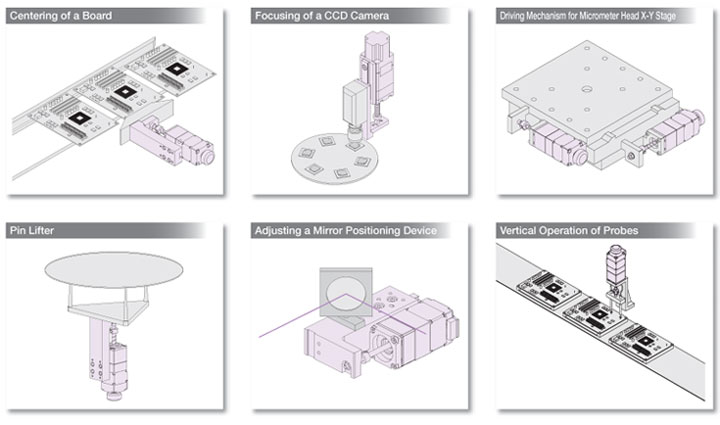
Application Examples
Guide Type
- 20 mm (0.79 in.)
- 28 mm (1.10 in.)
- 42 mm (1.65 in.)
- 60 mm (2.36 in.)
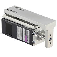
Compact linear actuators with built-in guide reduces the need for an external anti-spin mechanism further reducing parts required for designing your applications.
Ground Ball Screw
Ideal for applications where high positioning accuracy and low vibration are required, such as optical devices and semiconductor systems that use fine-feed pitches. The DRLII ground ball screw type achieves high reliability by maximizing the performance of a 5-phase stepper motor.
Rolled Ball Screw*
Ideal for general positioning applications where reliability and ease of use are given priority. It combines the superior thrust and resolution of the ground ball screw type with greater ease of use.
*Rolled Ball Screw type not available in 20 mm (0.79 in.) Frame Size
Standard Type
- 20 mm (0.79 in.)
- 28 mm (1.10 in.)
- 42 mm (1.65 in.)
- 60 mm (2.36 in.)
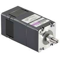
Compact linear actuators with built-in guide reduces the need for an external anti-spin mechanism further reducing parts required for designing your applications.
Ground Ball Screw
Ideal for applications where high positioning accuracy and low vibration are required, such as optical devices and semiconductor systems that use fine-feed pitches. The DRLII ground ball screw type achieves high reliability by maximizing the performance of a 5-phase stepper motor.
Rolled Ball Screw*
Ideal for general positioning applications where reliability and ease of use are given priority. It combines the superior thrust and resolution of the ground ball screw type with greater ease of use.
*Rolled Ball Screw type not available in 20 mm (0.79 in.) Frame Size
Motor Types
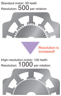
High Resolution (0.36°) and Standard (0.72°) Type Motors
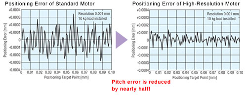
The high-resolution motors* achieve high accuracy and reliability based on Oriental motor's latest precision machining technology. The motor resolution is increased to double the level of a standard model to reduce the displacement angle against torque, thereby achieving high position accuracy. Frame sizes of 1.10 in. (28 mm), 1.65 in. (42 mm) and 2.36 in. (60 mm) are available.
In fine-feed operations by microsteps, the actuator will not operate until the initial motor torque exceeds the friction load. The high-resolution motor, with its high output torque, allows the torque to pick up quickly and thereby ensures smooth operation even with fine-feed.
*Ground Ball Screw Type Only
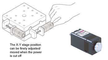
Adjustment Knob
- 20 mm (0.79 in.)
- 28 mm (1.10 in.)
- 42 mm (1.65 in.)
- 60 mm (2.36 in.)
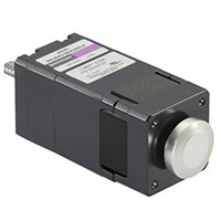
The load position can be adjusted manually when the power is cut off. This function is useful during servicing of the equipment.
Electromagnetic Brake
- 42 mm (1.65 in.)
- 60 mm (2.36 in.)
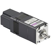
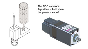
The load position can be held when the power is cut off. Since the work will not fall in case of power failure or disconnection, you can safely use equipment in which the work moves vertically.
Built-in Controller (Network Type)
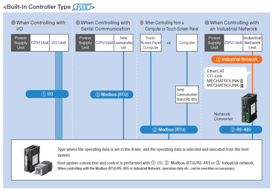
1. I/O
Because the positioning unit (pulse generator) function is built in to the driver, you can build an operation system using I/O by directly connecting to a switch box or PLC. Because a positioning unit is not necessary on the PLC side, space is saved and the system is simplified.

Using a Switch Box - Because operating data is set in the driver, the actuator can be started and stopped simply by connecting a switch you have on hand. Control can be performed easily without using PLC.
Using PLC - When using PLC you can build an operation system by connecting directly to an I/O unit. Because a positioning unit is not necessary on the PLC side, space is saved and the system is simplified.
Using PLC and a Touch Screen - Normally, the actuator is started and stopped with I/O. Changing the operating data settings and displaying the monitors and alarms is performed with the touch screen using Modbus (RTU) communication. When there is a lot of setup work, changes can be easily performed on the touch screen, and the burden of creating ladders is reduced.
2. Modbus (RTU) / RS-485
Operating data and parameters can be set and operation commands can be input using RS-485 communication. Up to 31 drivers can be connected to each serial communication unit. Also, there is a function that enables the simultaneous start of multiple axes. The protocol supports Modbus (RTU), enabling connection with devices such as touch-screen panel computers and PCs.
3. Industrial Network
Using a network converter (sold separately) enables support with EtherCAT communication, CC-Link communication, and MECHATROLINK communication. Operating data and parameters can be set and operating commands can be input using various communication methods.
Programming Options (for Built-in Controller Type)
Data Setting and Extended Functions
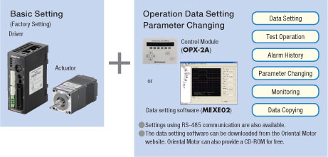
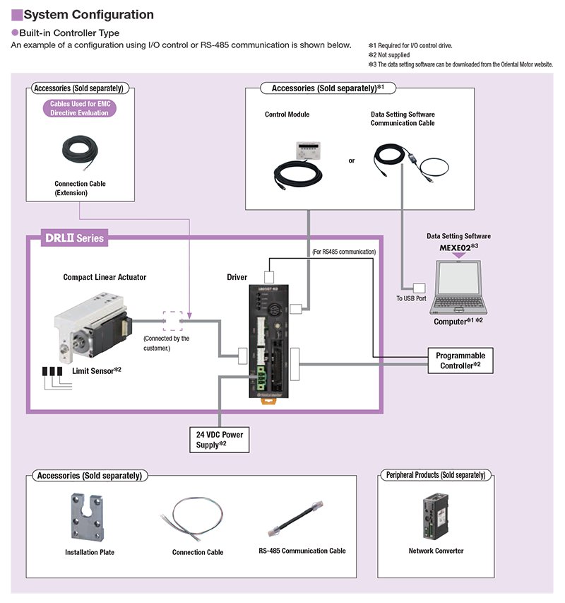
Because the driver has the information necessary for actuator operation, the burden on the host PLC is reduced. The system configuration when using multi-axis control has been simplified. Settings are configured using a control module (sold separately), data setting software or RS-485 communication.
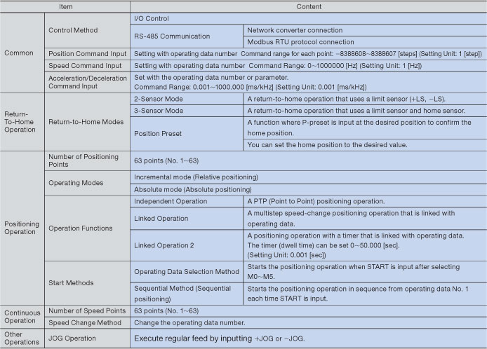
Operation Types
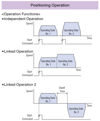
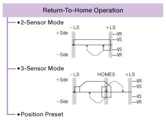
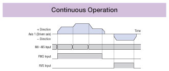
In the built-in controller type, the operating speed and traveling amount of the actuator are set with operating data, and operation is performed according to the selected operating data.
There are 4 operation types.
Group Transmission Function (via RS-485 communication or network converter)
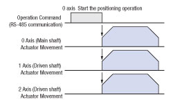
You can configure a group of multiple axes connected using RS-485 communication and send commands by group. You can also perform simultaneous operation for multiple axes.
PLS-OUT Output Function
Synchronous Operation Possible
This outputs signals with the same number of pulses and pulse speed as the command value.
The PLS-OUT signal and DIR-OUT signal (rotation direction signal) can be input to another driver to drive the actuator for another axis.
Used for Position Count
The command position to the actuator can be checked by counting the output signals.
Teaching Function
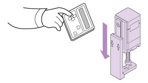
Teaching can be performed using the OPX-2A control module (sold separately) or the MEXE02 data setting software. Move the table to the target position and store the position data at this time as the positioning data.
Network Gateways
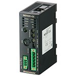
The communication protocol of the master controller, Factory Automation (FA) network, is converted to Oriental Motor's own RS-485 communication protocol. Connection to Oriental Motor's network compatible products is completed with one RS-485 communication cable.
- Compatible Networks:
CC-Link, MECHATROLINK-II, MECHATROLINK-III, EtherCat
*For use with Stored Data (Network) type
![]()
![]()
![]()
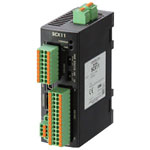
SCX11 Universal Controller
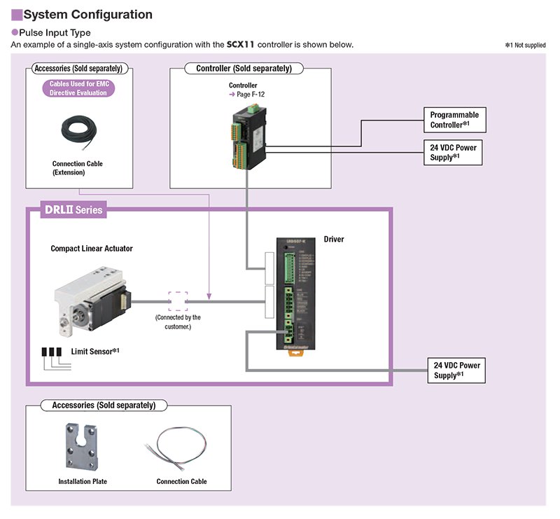
The SCX11 is a highly-functional and sophisticated controller equipped with program editing and execution functions. Use the SCX11 as a stored program controller to connect to any of Oriental Motor's standard pulse input drivers. The SCX11 is also able to control the motor via serial communications such as USB, RS-232C and CANopen.
*For use with Pulse Input Type driver.
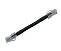
RS-485 Communication Cable
These cables are used to link drivers when a built-in controller type is being operated in a multi-drop manner.
*For use with Stored Data (Network) type
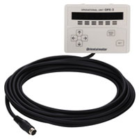
Control Options - Control Module
The internal driver parameter settings and data settings can be established and changed. They can also be used for speed and I/O monitoring, teaching, and so on.
*For use with Stored Data (Network) type
Control Options - Support Software
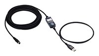
This communication cable is required for connecting to the computer on which the data setting software is installed.
System Configuration
CAD / Manual Search
To locate product CAD and Operator Manuals please search using the product Item Number.
