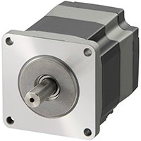
The αSTEP AZ Series Stepper Motor Advantage: Eliminating External Sensors
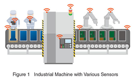
Sensing technology is everywhere today. Sensors are used to detect human touch on a smart phone, ambient temperature in a room, and even in non-invasive blood glucose measurement for diabetes detection. In this paper, we will focus on the most commonly adopted external sensors used specifically for homing and limiting motor operations.
For many reasons, it might make more sense to use a built-in sensor that is already integrated into a component of a machine, such as a motor. Our new AlphaStep AZ Series motors offer a patented, built-in position tracking sensor which can eliminate most external sensors discussed in this paper as well as offer an alternative to better performance for machine designers.
Let’s start by learning the basic features of these sensors and their necessary design considerations in order to better understand the benefits of a built-in sensor.
What is a Sensor?
In the most general term, sensors are devices that convert a physical parameter (temperature, humidity, speed, distance, etc.) into an electrical signal which can be used by the controls system for verification purposes. In industrial automation, mechanical switches and presence sensors are the types of sensors used to determine the presence or absence of the physical moving load at specific locations. If a machine process becomes unstable, it is necessary for the motors to move back to its “home” position in order to restart its operation.
The Importance of a Homing Operation
In a CNC router or 3D printer where high position accuracy is required, a “home” or "zero" position is critical for a servo or stepper motor to start counting its “steps” from. Even for motors with incremental encoders, an external mechanical switch or presence sensor is necessary to physically determine the home position reliably. Without a home position, the motors could start from any rotational angle and any subsequent movement would be inaccurate. To ensure safety or to avoid damage, more sensors would be required to determine upper and lower "limits" in order to restrict the motor movement. If any "limit" sensor is triggered, the machine will alarm out, and a "homing" operation is required to reset the motors back to its starting position.
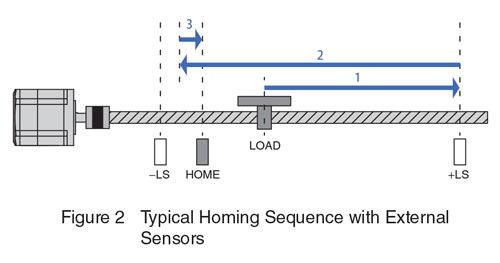
Figure 2 shows a typical homing sequence for a motor coupled with a ball/lead screw for linear movement. There are 3 sensors: -LS, HOME and +LS. First, notice that the motor is not exactly at the HOME sensor. At this time, the motor is commanded to start its normal operation in the forward direction towards the +LS sensor. Since the motor is not where it's supposed to start from, it will eventually move the LOAD outside of the intended range of operation and trigger the +LS limit sensor. When that happens, the motor will need to reverse direction and move the LOAD towards the HOME sensor to reset itself. Once it triggers and passes the HOME sensor, the motor will reverse its direction back to the HOME sensor until it’s triggered again. At this time, the motor stops and the homing sequence is completed. Now the motor is ready to restart its intended operation from its proper "home" position.
Mechanical Switches & Presence Sensors
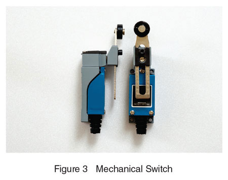
Mechanical switches, also known as limit switches, work like a light switch, and are commonly used for industrial automation.
Mechanical switches are simple electromechanical devices where an actuator is mechanically linked to a set of electrical contacts.
When an object or load comes into contact with the actuator on the mechanical switch, the contacts close (or open) in order to make (or break) an electrical connection which can be used as a verification signal. Since mechanical switches have the most moving parts, additional design consideration is necessary to allow for future maintenance. The main difference between limit switches and other types of presence sensors is that limit switches require physical contact from the moving load. They also require the most space for installation.
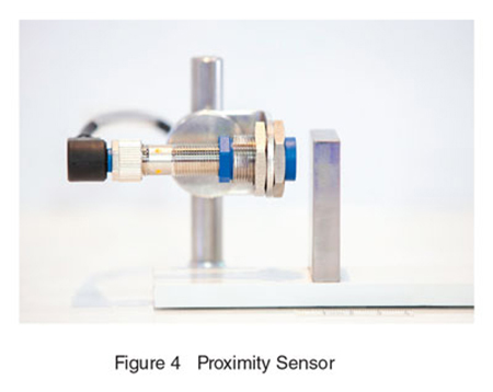
Proximity sensors are a type of presence sensor. Depending on the type of the proximity sensors used, a “flag” may be necessary on the moving load in order to work. A “flag” is the part on the load that can be easily detected by the sensor.
A proximity sensor generally emits an electromagnetic field and looks for changes in the field. Once it detects a change in the field, it can then output an electrical signal to a motion controller or PLC. Proximity sensors include 2 types: Inductive and Capacitive. An inductive proximity sensor can detect ferrous metal objects. This is typically where a “flag” would be used. A capacitive proximity sensor can detect non-metal objects, but the technology costs more. Proximity sensors are fairly easy to install and operate, and they can operate in harsh environments. Their range of detection is typically 1~10 mm. For longer ranges, larger sensors are necessary. Repeatability is not great at 0.1~0.5 mm, and temperature can affect the sensing accuracy.
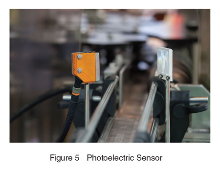
Photoelectric sensors are another type of presence sensor that emits light which can be visible or infrared, and looks for a deflected signal on a receiver. Once the receiver detects a sufficient light signal which is deflected from a flag on the load, it can then send an electrical signal to the motion controller or PLC.
Photoelectric sensors are ideal for high accuracy positioning and good repeatability because they offer great sensing accuracy at below 1 mm. Since these sensors use optics, they are good for sensing at longer distances than other types of sensors, but they are sensitive to harsh environments. For example, dust can degrade the optical system used in these sensors. Alignment can also be an issue that needs further consideration.
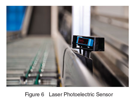
Laser type photoelectric sensors provide the best characteristics such as long distance sensing and accuracy but with increased cost. Lasers offer accuracy at the sub-micron level (less than 0.001 mm), high repeatability and longer detection range than other sensors. Some laser sensors allow the exact detection range to be programmed. Since we’re dealing with lasers, precautions need to be considered to prevent direct contact with the human eye. For laser sensors, alignment needs to be very precise.
Design Criteria for Sensor Selection
Traditionally, motors were sized for the application first before the controls system is designed. Recent market demand for IIOT (Industrial Internet of Things) communication is reversing this process. Now PLC’s (Programmable Logic Controllers) or some form of HMI (Human Machine Interface) are often selected first, then components such as electric motors, drives, motion controllers and/or sensors are integrated to the PLC or HMI either by discrete I/O or field bus network. It’s important to consider all machine components early in the design process rather than later.
To determine what type of sensors you need for your application, some of the criteria you’ll need to consider first is accuracy, environmental limits, measurement range, calibration, resolution, cost and repeatability. Since sensors will eventually need to be replaced, you will need to determine sensor locations that are easy to service as well as necessary cable lengths. Sometimes, terminal blocks may be necessary to extend the sensor signals. Since each sensor requires wiring for power and output, 10 sensors used for an industrial machine uses 40 wires, further investment in labor hours is necessary to assemble connectors and cables.
Sensors Need to be Integrated
After you have confirmed the type of sensors needed for your application, compatibility with the PLC is required. These sensors need to meet the input circuit specifications of the motion controller or PLC selected in the machine design. Some of these specifications are ON/OFF state, voltage levels, current requirements or even network protocols. A common inquiry often involves determining what type of sensors are compatible, and how to wire the sensors. An example is if your PLC only accepts NPN output type sensors, you cannot use a PNP output type sensor. You also need to consider if you’re working with a normally open or normally closed circuit.
Cost of External Sensors
Before you can build the sensor circuit, you need to first come up with the Bill of Materials. These not only include the right type and number of sensors, but you’ll also need to determine the necessary cable lengths, cable holders mounting brackets and connectors. You may also have to build some of it yourself. At the same time, your machine design needs to consider compatibility and space for all of the required components.
Limit switches are the most inexpensive type of sensing device. They are offered at a wide range of pricing starting from under $1. However, they also fail the most.
Proximity sensors cost between $3 and $30. They’re fairly easy to install and use and can withstand harsh environments. However, you need to often use a metal “flag” on the moving load, and temperature or external magnetic fields can affect the sensing accuracy.
Photoelectric sensors are more expensive at $40~$150 (more for laser type) and may require additional amplifiers which adds to the total cost. They are sensitive to their environment and alignment. However, they offer the highest accuracy, best repeatability and longest sensing range.
A study with one of our own factory production machines revealed that for 3 axes of XYZ motion, 9 sensors ($10 each), 9 cables ($10 each), 3 dogs ($1 each) and 3 sensor rails ($5 each) were required for a total cost of $198. This machine also includes other components such as cameras and air supply which also require cables so design of cable locations is also important.
Testing
The next step is to actually test the sensors to confirm if they work as intended. You need to verify if the sensor is installed in the proper location in order to determine the correct position. This typically requires repeated tests of the homing operation for the motor. This is time consuming because a homing operation needs to be performed at a slower speed than normal operation.
After you have confirmed that your sensor system works as expected, you will also need to plan a maintenance schedule to prevent field failures.
Maintenance
As with any electrical or mechanical component, these sensors need to be replaced from time to time depending on the environment and usage. If one sensor fails, it makes the whole machine process unreliable. Machines need to be shut down which means less production and less profit for your company. You will also need maintenance engineers who have the skills and experience to help prevent these failures or resolve these problems when they unexpectedly occur.
Maintenance schedules vary due to the type of sensor selected. Some sensors are sensitive to their environment more than others. Factors such as dust and oil can decrease the life of a photoelectric sensor. Alignment of the sensors need to be regularly checked especially if it’s a laser sensor. Chattering from the motor mechanism could cause sensors to shift over time.
While we’re on the topic of maintenance, it’s useful to know that real-time monitoring functions are standard on our AZ Series drives. Real-time stored drive data such as alarm history, input voltage, motor position, speed, temperature, and torque can be accessed through discrete I/O or a field bus network. Knowing the status of your motor and drive is helpful in planning your maintenance schedule or for troubleshooting.
The AZ Series Advantage
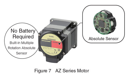
As mentioned in the beginning of the article, sometimes it may make more sense to use a motor with a built-in position tracking sensor, such as an encoder. Our AZ Series closed-loop stepper motors features a built-in absolute mechanical sensor on the back of the motor which can serve the same function as an absolute encoder and offer the ability to eliminate the need for external sensors.
This multi-rotation position sensor is integrated to the back of the AZ motor and works with its dedicated drive in tracking the absolute position of the motor and providing fast, reliable homing.
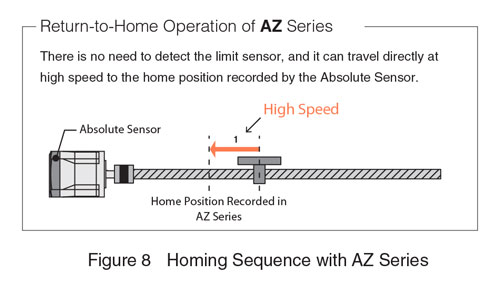
The ability to track the absolute position of a motor is becoming increasingly important in industrial automation as production efficiency requirements become more demanding. Without an absolute position sensor in your machine, it means that motors could lose its known position, and the motor operation will need to restart from the beginning again. During this time, your machine is not producing and may even produce defective products. With the AZ Series, there is no need to detect the external home sensor, and it can travel directly at high speed to the home position recorded by the absolute mechanical sensor.
How Does the AZ Sensor Work?
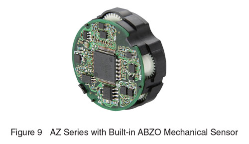
The technology of this new absolute mechanical sensor is based on a magnetic resistive sensing technology which is referred to as an ABZO sensor (shown in figure 9). These sensors can detect the angle of magnetic fields though electrical resistance.
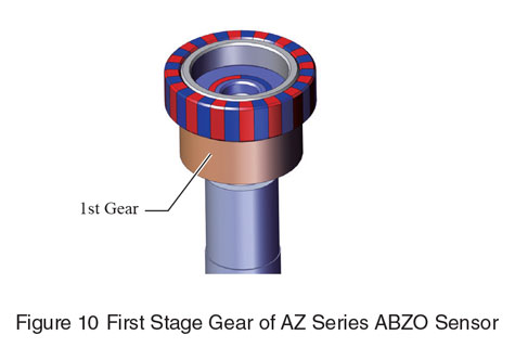
Structure of the built-in absolute mechanical sensor includes a main 1st stage toothed gear which is connected to the rotor (rotating component of a motor), then a series of toothed gears are also connected to the 1st stage gear.
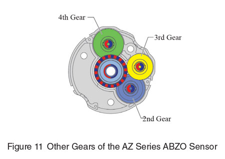
All gears have magnets mounted on specific locations. Since the number of teeth is different among these gears, the magnets mounted on these gears would be pointed in different directions. The magnetic resistive sensors mounted on the circuit board (also on the back of the motor) can determine the angles of the magnetic fields generated by the magnetic poles on these gears, then the absolute position of the rotor is calculated with an algorithm similar to the concept of the hour, minute and second hands of a wall clock. Up to 1800 motor revolutions of absolute positions can be tracked accurately and reliably.
Since an absolute home position can be set and stored in non-volatile memory easily by a push button or a software click, external sensors are not necessary.
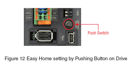
Along with the elimination of external sensors, issues with all types of sensors such as wiring, testing and maintenance are also removed from your machine design; resulting in less problems to worry about. To withstand demanding environments, the AZ Series motors also feature an IP66 rating which is both dust-proof and water-proof.
Some servo motors are equipped with absolute encoders, however, many of them are optical in nature and require the use of battery power. Since our sensor is mechanical in nature, battery power is not necessary. After a power failure, our AZ Series motors can resume operation immediately without the need to perform a homing operation.
With our patented Alpha Step Keep-in-Step technology, the AZ Series features a self-contained position correction function (similar to a servo motor system) to avoid missed steps. This ensures additional position accuracy and peace of mind for positioning applications. This technology also uses the motor’s position sensor to optimize timing of phase switching within the motor windings for the best performance. For the next section, we will show some actual test data for comparison of stop accuracy.
Homing Stop Accuracy Comparison
Now let us compare the homing stop accuracy when using external sensors vs using our AZ Series stepper motors.
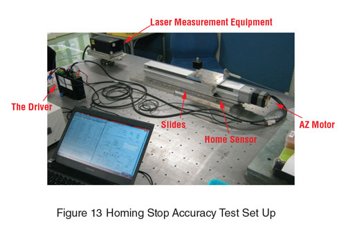
Our test setup includes an AZ motor installed on one of our linear slides, an AZ dedicated drive, an external photoelectric sensor, and a laser distance measurement device. We then performed tests and recorded the error in mm vs time in seconds. The different colors show different RPM used for the test.
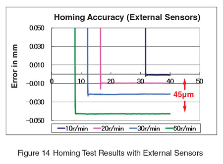
First, we tested the homing operation with the photoelectric sensor at different speeds. It’s important to notice in figure 14, higher speeds lead to less stop accuracy. This is because at higher speeds, it takes longer for the sensor to stop the motor completely. At 60 RPM, we are seeing an overshooting error of between 0.03 and 0.05 mm. From 10 to 60 RPM, we have a variation of stop accuracy of about 45 microns.
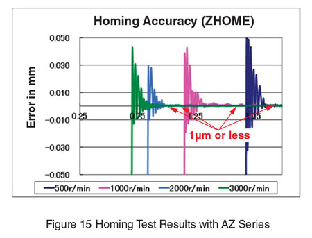
When we perform the same homing operation with the AZ Series without the external sensor, we can offer a stop accuracy of 3 arc minutes at speeds up to 3000 RPM. This means you can expect a faster and more consistent stop accuracy to help increase throughput of the machine. As shown in figure 15, once the AZ motor settles to a stop, the stop accuracy is 1 micron or less.
Summary
In summary, there are many factors to consider when selecting and maintaining external sensors such as characteristics of the sensors, environmental limitations and specifications. We also discussed issues related to external sensors such as a wiring, maintenance and inconsistency in stop accuracy. A machine builder needs to invest more time or hire more staff in order to ensure every component is integrated and maintained properly to ensure efficient production from the machine.
With the current trend striving towards engineering efficiency and faster product development, the AZ Series stepper motors with built-in position sensors eliminates many issues associated with external sensors and provides an ideal integrated product solution for industrial machine applications. Schedule a demo with our OEM sales team today to learn more about the AZ Series.
