BLV Series R Type Brushless DC Motors (BLDC Motors) (DC Input)
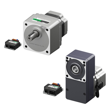
BLV Series R Type Brushless DC Motors (BLDC Motors) (DC Input)
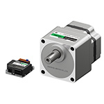
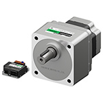
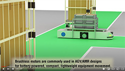
The BLV Series R Type brushless DC motor (BLDC motor) speed control system offers the design of motor and driver significantly reduced in size and weight, yet high-power, and contributes to the battery driven automation.
- Battery-operated
- Compact and Lightweight
- Speed Range: 1:4000 r/min
- Communication through Modbus (RTU) and CANopen
- DC Voltage range: 15 VDC~55 VDC
- Load Holding (Positioning) when stopped
![]()
Brushless DC Motor (BLDC Motor) & Gear Motor Lineup
Output Power |
Gear Options |
Available Options |
Power Supply |
Rated Torque |
Speed Range* |
|
Parallel Shaft |
- | 24 - 48 VDC |
8 ~ 142 lb-in |
0.86 ~ 16 N·m |
1 ~ 4000 r/min Min: 0.005 [200:1] |
|
| CS Geared | 8 ~ 30 lb-in |
0.86 ~ 3.4 N·m |
||||
Hollow Shaft Flat |
7 ~ 288 lb-in |
0.81 ~ 32.5 N·m |
||||
Round Shaft (no Gear) |
32 oz-in |
0.191 N·m |
||||
Parallel Shaft |
Electromagnetic Brake | 24 - 48 VDC |
25 ~ 240 lb-in |
2.9 ~ 27.4 N·m |
1 ~ 4000 r/min Min: 0.005 [200:1] |
|
Hollow Shaft Flat |
23 ~ 470 lb-in |
2.7 ~ 54 N·m |
||||
Round Shaft (no Gear) |
45 oz-in |
0.319 N·m |
||||
Parallel Shaft |
Electromagnetic Brake | 24 - 48 VDC |
50 ~ 450 lb-in |
5.7 ~ 51.6 N·m |
1 ~ 4000 r/min Min: 0.01 [100:1] |
|
Hollow Shaft Flat |
47 ~ 470 lb-in |
5.4 ~ 54 N·m |
||||
Round Shaft (no Gear) |
90 oz-in |
0.637 N·m |
||||
Parallel Shaft |
Electromagnetic Brake | 24/48 VDC |
101 ~ 487 lb-in |
11.4 ~ 55 N·m |
1 ~ 4000 r/min Min: 0.01 [100:1] |
|
Hollow Shaft Flat |
96 ~ 956 lb-in |
10.8 ~ 108 N·m |
||||
Round Shaft (no Gear) |
176 oz-in |
1.27 N·m |
||||
Brushless DC Motors (BLDC Motors)
BLV Series R-Type
High-Power, Compact Brushless Motors. Developed to Support the Design of Compact, Battery Driven Automation.
Compact, Lightweight Motor and Driver
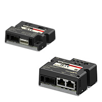
Both the motor and driver are significantly smaller and lighter. The driver is approximately 80% smaller than the conventional product. The smaller driver saves valuable space in the automation equipment.
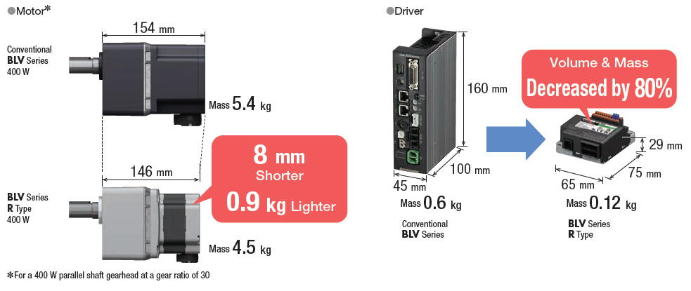
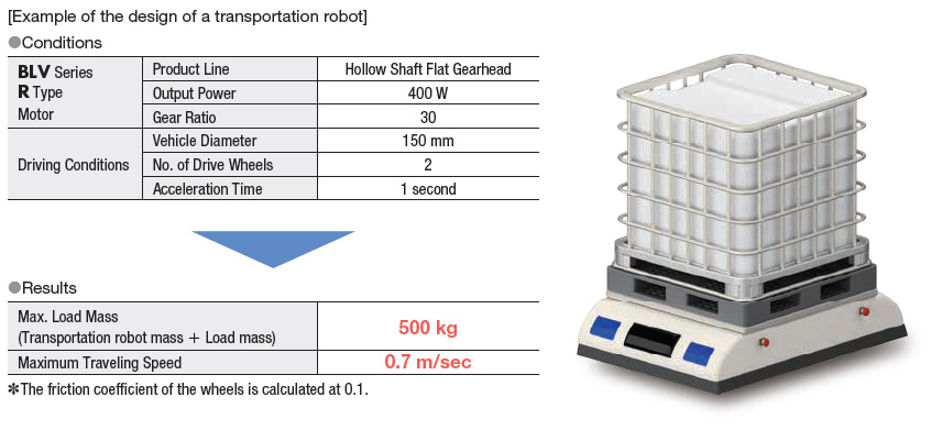
Powerful
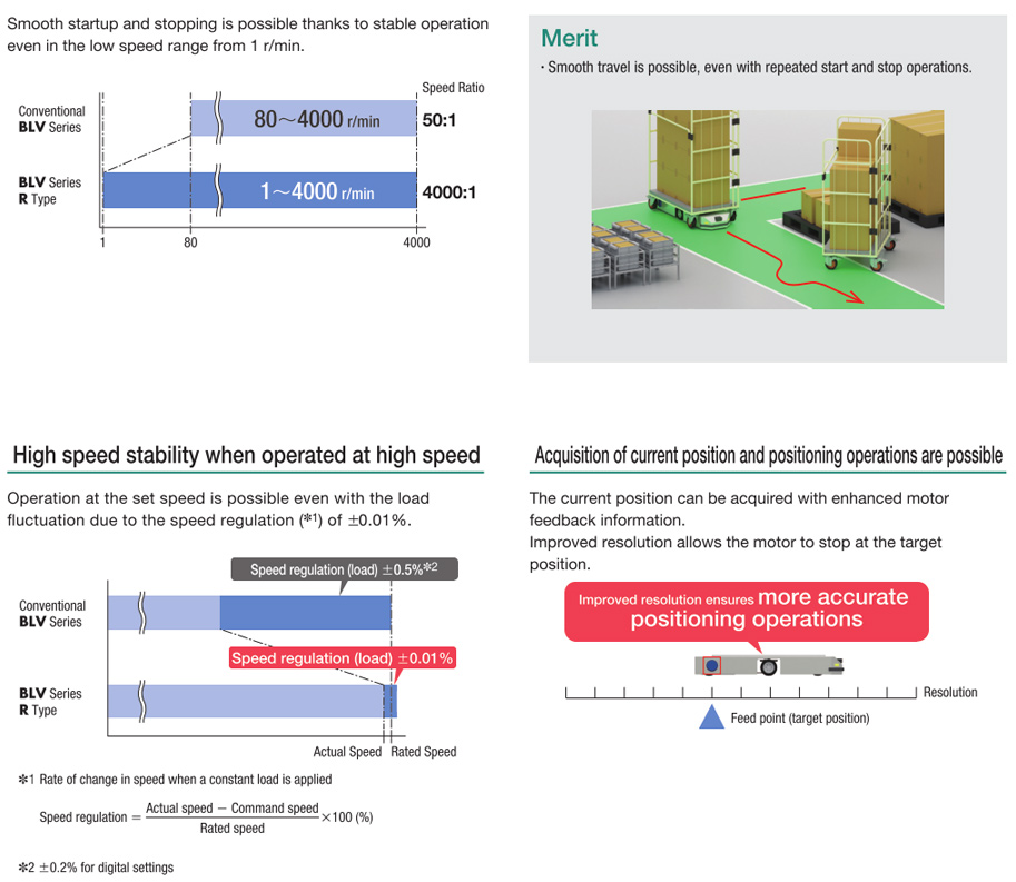
Wide Speed Range, Smooth Motion, Current Position and Position Feedback is Possible.
- Broad speed control range of 1∼4000 r/min. Smooth performance is possible throughout the entire speed range.
- Current position and position feedback is possible from increased motor resolution.
Wider Range of Operating Voltage
Compatible with 24∼48 VDC batteries.
Will not stop even if the battery voltage drops. Continues operating while limiting the speed and torque.
- The driver's overvoltage alarm threshold is 63 VDC
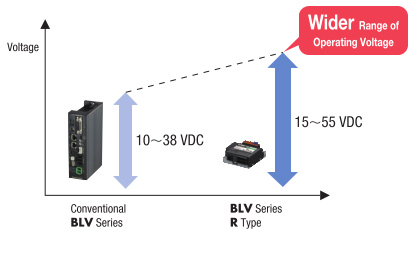
*400 W type is 48 VDC, operating voltage range is 30 ~ 55 VDC
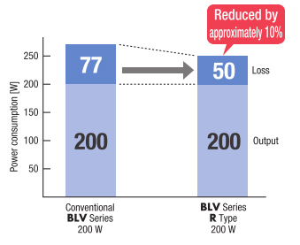
Power Consumption Reduced by 10%
Extended travel distance and time for transportation robots.
The number of battery charges can also be decreased.
Power consumption can be monitored via the MEXE02 Support Software
and communication.
Holding when Stopped is Possible without an Electromagnetic Brake
When the motor has stopped in an excitation state, it can be used as an electrical holding brake even without a mechanical brake.
The motor enters an excitation state when the input signal “S-ON” is turned ON, and generates holding force. (Servo ON)
When the input signal “PLOOP-MODE” is turned ON, the position can be held with no deviation from the stop position.
NOTE: If the power supply to the driver is turned OFF, the holding force dissipates. This cannot be used to prevent a fall during a power outage.
ATL Function that Automatically Limits Output Torque
The ATL function limits torque and ensures that the motor does not stop when an overload alarm occurs, even when torque continues to be output at a level at which an overload alarm is detected. The motor will continue driving even if an unexpected overload occurs.
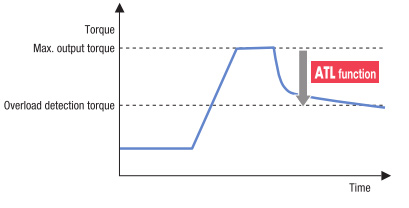
*Examples
- Running into an obstacle
- Sudden acceleration command
- Carrying a load exceeding the transportable mass
Please disable the ATL function if the motor should stop when an alarm is output during overload.
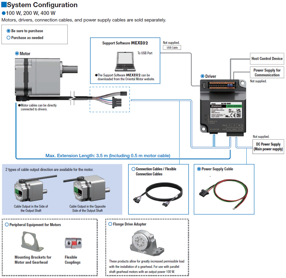
Cable Output Direction Can be Selected
There are two motor cable output directions to choose from according to the equipment.
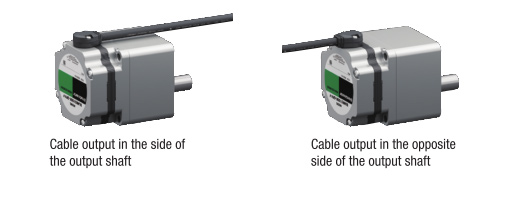
Can be used for various applications, including transportation robots.

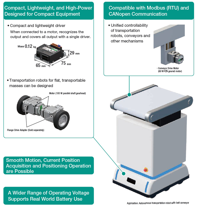
Compatible with Modbus (RTU) and CANopen Communication
The BLV Series R Type is compatible with the two interfaces of Modbus (RTU) and CANopen communication.

Main Functions with Modbus (RTU)
Freely Create Operation Profiles - Direct Data Operation
With Modbus (RTU) communication, data can be rewritten and operations can be started at the same time.
Types of Operating Data
| Operating Modes | Sets the operating mode. |
| Position | Sets the target position. |
| Speed | Sets the operating speed. |
| Acceleration Rate | Sets the acceleration time. |
| Deceleration Rate | Sets the deceleration time. |
| Torque Limiting Value | Sets the torque limiting value. |
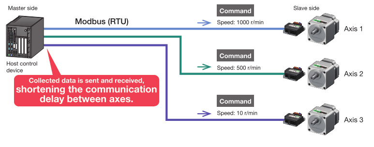
Gather, Send and Receive Data Across Different Axes - ID Share Mode
This function improves synchronization between axes with Modbus (RTU) communication.
Data collected from multiple axes can be sent and received, shortening the communication delay between axes.
It can also be used to send different commands to each axis at the same time.
This transmission method is unique to Oriental Motor.
Support from Startup and Operation to Maintenance
By using the Support Software MEXE02, data setting, actual operation, and confrmation via each monitor can be performed easily on a computer.
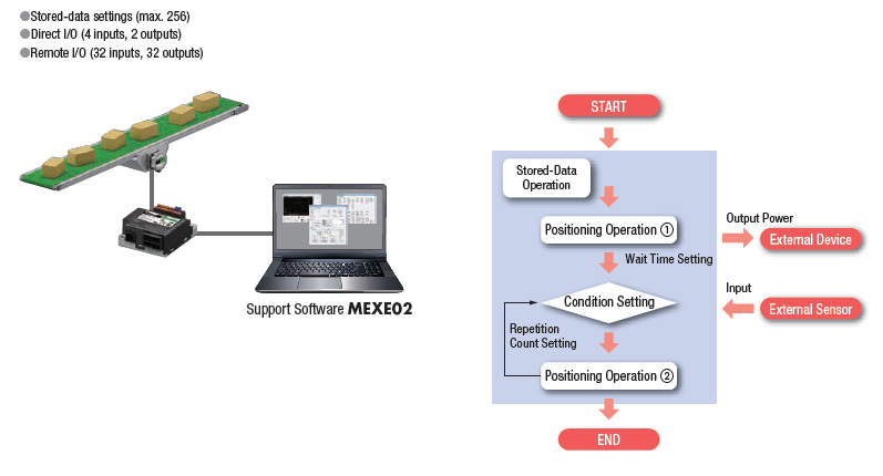
Simplified Main Program Thanks to Sequence Function
Can be used during stored-data operation, and comes with many sequence functions such as a timer setting for between operations and linked operation, conditional branching, and loop count. These help simplify the host system's sequence program.
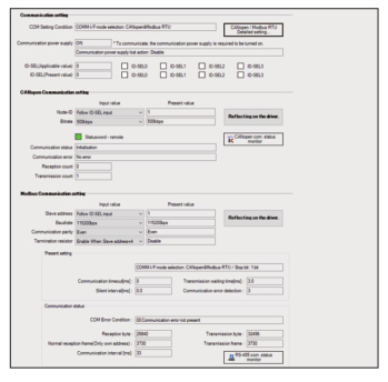
Simple Settings
Various communication settings can be easily made using the “Simple communication settings”.
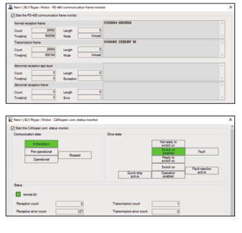
Communication Frame Monitoring, Communication Status Monitoring
All communication frames and statuses can be monitored.
This is useful for host program startup and debugging.
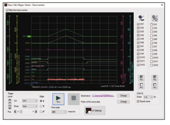
Waveform Monitoring
The operating status of the motor (command speed, torque, I/O signal, etc.) can be checked like an oscilloscope.
Waveform measurement results can be saved as images and in CSV format.
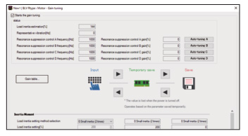
Gain Tuning
Motor tracking can be adjusted according to the command.
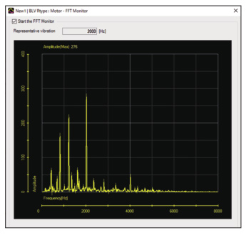
FFT Monitoring
Visualizes mechanical resonance by analyzing frequency using FFT analysis. Noise and vibration can be reduced by adjusting the resonance suppression parameter.
Trace Monitoring
The operating status of the motor can be continuously measured for 24 hours or longer.
Data can be saved in CSV format. Data is saved for a long period of time, making it easy to determine the cause of a problem.

Long-Life, Parallel Shaft Gearhead
- 60 W (1/12 HP)
- 100 W (1/8 HP)
- 200 W (1/4 HP)
- 400 W (1/2 HP)
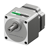
The high-strength gearhead is designed to withstand high-speed revolutions. The rated life of the gearhead is 10000 hours, which is twice as long as that of our previous gearhead.
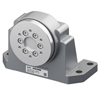
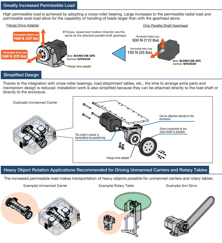
Flange Drive Adapter available for 100 W (1/8 HP) Parallel Shaft Gear Motors
Permissible load has been increased by mounting with a parallel shaft gearhead. Direct mounting of the rotation mechanism to wheels or rotary tables has been simplified, which helps reduce design time.
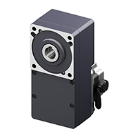
Hollow Shaft Flat Gearhead
- 60 W (1/12 HP)
- 100 W (1/8 HP)
- 200 W (1/4 HP)
- 400 W (1/2 HP)
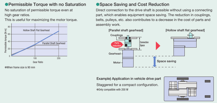
Permissible Torque without Saturation
The hollow shaft flat gearhead enables permissible torque without saturation even at high gear ratios. The motor torque can be fully utilized.
Space Saving is Achieved with a Hollow Shaft Flat Gearhead
The output shaft can be coupled directly to your drive shaft without using a coupling. The flexible installation modes, such as installation on either the front or rear face or by using the center shaft, allows you to reduce the size and installation space of your equipment. Since no shaft-coupling parts are needed, the parts cost and assembly man-hours will also decrease.
CS Geared Motor
- 60 W (1/12 HP)
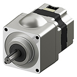
CS geared motors feature increased load capacity, upgraded torque, and coaxial shaft.

Electromagnetic Brake
- 100 W (1/8 HP)
- 200 W (1/4 HP)
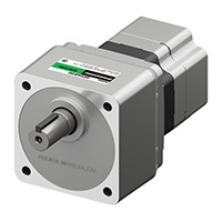
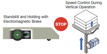
Electromagnetic Brake Models Available for Vertical Drive
The type with an electromagnetic brake is suitable for position holding during standstill and gravitational operation. Note that there are power supply restrictions when using during vertical operation (gravitational operation).
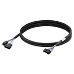
Connection Cables
These cables are used to connect the motor and the driver.
Keep the overall length of the cable at 3.5 m or less.
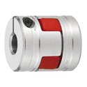
Flexible Couplings
These products are clamp type couplings used to connect a motor or gearhead shaft to the shaft of the equipment.
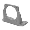
Mounting Bracket
This is an aluminum die cast mounting bracket for geared motors.
Long, horizontal holes make it easy to make fine adjustments during installation.
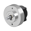
Rotary Encoders
Small, thin, and lightweight stand-alone rotary encoders with an outer diameter of ϕ30 mm can be installed in tight spaces.
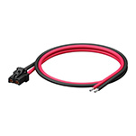
Power Supply Cable
This cable is used to connect the driver and the DC power supply.
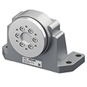
Flange Drive Adapter
Permissible load has been increased by mounting with a parallel shaft gearhead. Direct mounting of the rotation mechanism to wheels or rotary tables has been simplified, which helps reduce design time.
*For use with 100W Parallel Shaft Gear Motors
Support Software
By using the Support Software MEXE02, data setting, actual operation, and confrmation via each monitor can be performed easily on a computer.
System Configuration
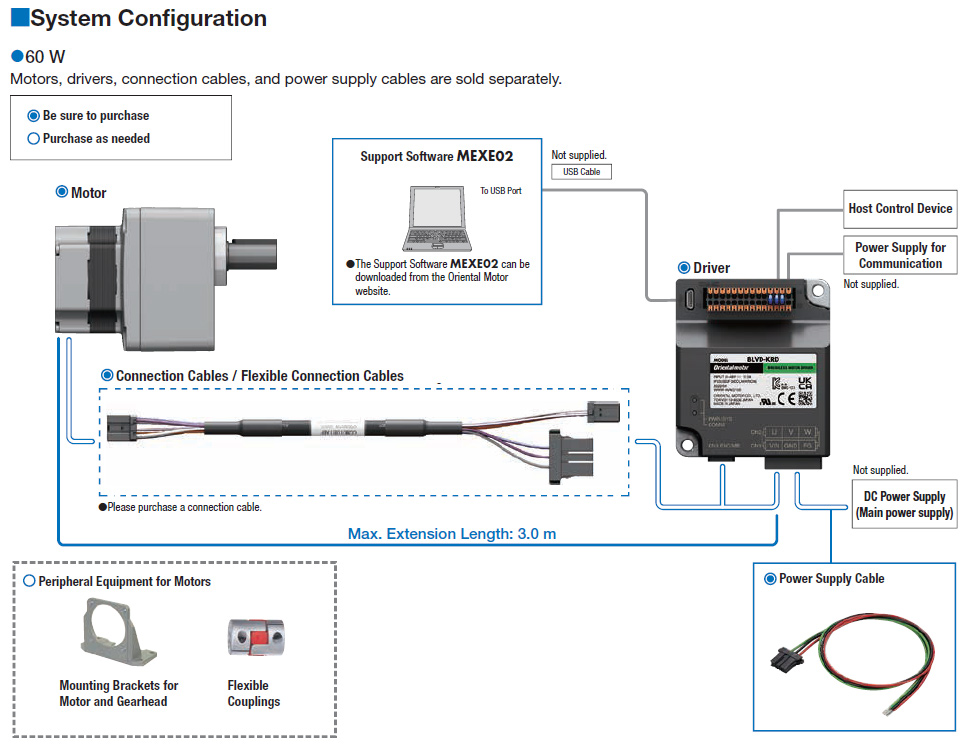
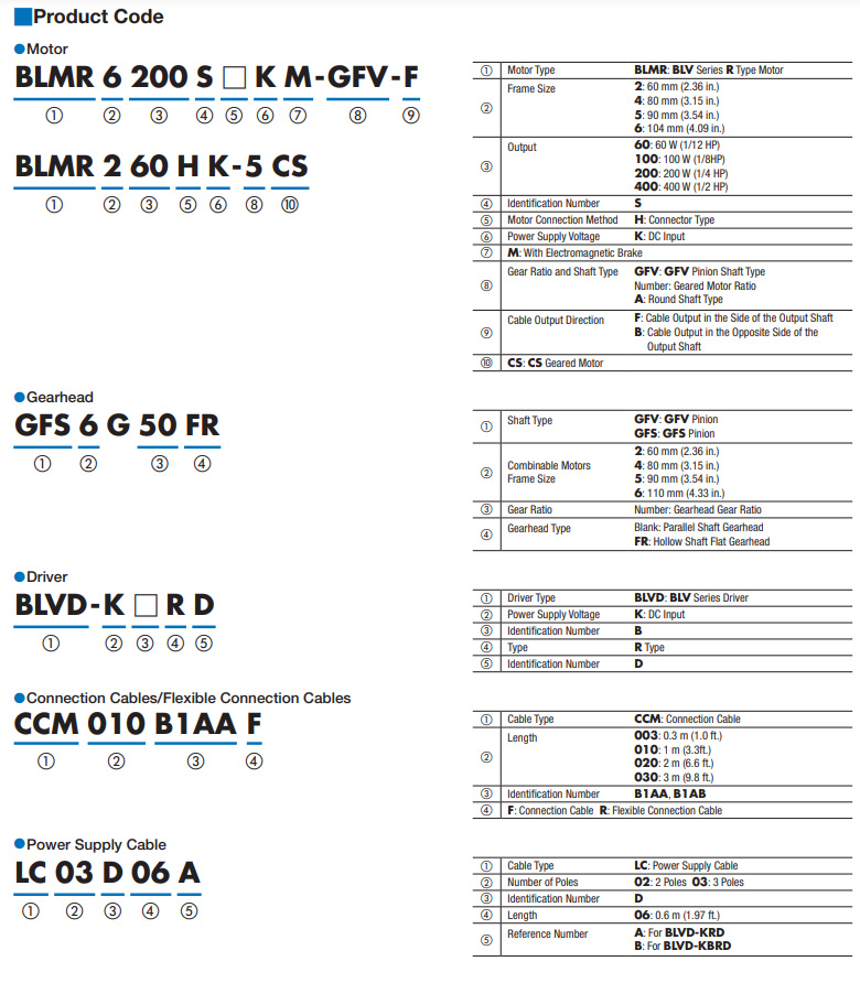
Part Number Code
CAD / Manual Search
To locate product CAD and Operator Manuals please search using the product Item Number.
