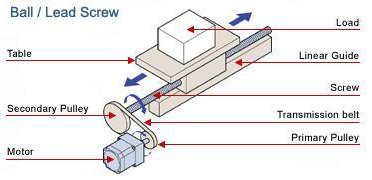
Ball / Lead Screw Application

Ball / Lead Screw Application

Unit

Select the unit

Load and Linear Guide

Total weight mass of loads and table

W m

= lb kg

Friction coefficient of the guide

μ

=

Ball / Lead Screw Specifications

Diameter

DB

= in mm

Total length

LB

= in mm

Lead (pitch)

PB

= in/rev mm/rev

(Distance the screw moves in one rotation)

Efficiency

η

=  %

ref; ballscrew 80 〜 95%,


leadscrew 30 〜 70%,

Material

ρ

=

Breakaway torque of the screw

TB

= lb·in N·m

External Force

FA

= lb N

Direction of Operation

Transmission Belt and Pulleys or Gears (Leave the fields blank if a direct coupling structure is used) 

Primary pulley (gear) pitch circle diameter (PCD) or diameter

Secondary pulley (gear) pitch circle diameter (PCD) or diameter

Dp1

=   in mm

Dp2

=   in mm

Primary pulley (gear) weight mass

Secondary pulley (gear) weight mass

Wp1 mp1

=   lb kg

Wp2 mp2

=   lb kg


If you are not sure about the weight mass

If you are not sure about the weight mass

Primary pulley (gear) thickness


Secondary pulley (gear) thickness

Lp1

=   in mm


Lp2

=   in mm

Primary pulley (gear) material


Secondary pulley (gear) material

ρp1

=


ρp2

=

Mechanism Placement

Mechanism angle

α

= °

Mechanism Angle

Other Requirement(s)

It is necessary to hold the load even after the power supply is turned off.
→ You need an electromagnetic brake.

It is necessary to hold the load after the motor is stopped, but not necessary to hold after the power supply is turned off.

Operating Conditions

Operating speed

V1

=

  in mm /s


Acceleration/Deceleration

t1

=

  s

Operating speed

V1

=

  in mm /s

V2

=

  in mm /s


Acceleration/Deceleration

t1

=

  s


Rotor inertia

JO

=

  oz·in kg·m 2


Gear ratio

i

=


If the rotor inertia and the gear ratio are unknown, the acceleration torque will be calculated with an inertia ratio of 5:1 (see the motor selection tips that will appear on the result window for the detail).

Positioning

Positioning distance

L

=

in mm

Positioning time

t0

=

 s    

Stopping time

ts

=

 s

If a specific acceleration / deceleration time is required

t1

=

 s

If a specific operating speed is required

V

=

  in mm /s

If Positioning distance is given and acceleration/deceleration is unknown, it is calculated as one fourth of Positioing time.

Stopping Accuracy

Stopping accuracy

±

in mm

Safety Factor

Safety factor


The following is the estimated requirements. Please contact 1-800-468-3982 ( from overseas 1-847-871-5931 ) for assistance or questions.

Sizing Results


Load Inertia 

JL

= [oz·in [kg·m 2]


Required Speed 

Vm

= [r/min]


V2

= [r/min]


Required Torque 

T

= [lb·in] = [oz·in] [N·m]


RMS Torque 

Trms

= [lb·in] = [oz·in] [N·m]


Acceleration Torque 

Ta

= [lb·in] = [oz·in] [N·m]


Load Torque

TL

= [lb·in] = [oz·in] [N·m]


Required Stopping Accuracy

Δθ

= [deg]


Other Requirement(s)


To print the calculation report, click    Full Report

To view the motor selection tips, click    Tips


×

Call 1-800-GO-VEXTA(468-3982) or 1-847-871-5931

Print Print

- given information -

Load and linear guide


Total weight mass of loads and table

W m

[lb] [kg]


Friction coefficient of the guide

μ

Ball/Lead screw specifications


Diameter

DB

[in] [mm]


Total length

LB

[in] [mm]


Lead (pitch)

PB

[in/rev] [mm/rev]


Efficiency

η

[%]


Material

ρ

[oz/in [kg/m 3]


Breakaway torque of the screw

TB

[lb·in] [N·m]

External force


FA

[lb] [N]

Transmission belt and pulleys or gears


Primary pulley (gear)

Secondary pulley (gear)


pitch circle diameter (PCD)

Dp1

= [in] [mm]

Dp2

= [in] [mm]


weight mass

Wp1 mp1

= [lb] [kg]

Wp2 mp2

= [lb] [kg]


thickness

Lp1

= [in] [mm]

Lp2

= [in] [mm]


material

ρ

= [oz/in [kg/m 3]

ρ

= [oz/in [kg/m 3]


Mechanism Placement


Mechanism angle

α

= [°]

Other requirement(s)


Is it necessary to hold the load even after the power supply is turned off?


Is it necessary to hold the load after the motor is stopped, but not necessary to hold after the power supply is turned off?

Operating conditions


Fixed speed operation

Operating speed

V1

=

[in/s] [mm/s]


Acceleration / deceleration time

t1

=

[s]

Operating conditions


Variable speed operation

Operating speed

V1

=

[in/s] [mm/s]


V2

=

[in/s] [mm/s]


Acceleration / deceleration time

t1

=

[s]

Operating conditions


Positioning operation

Rotor inertia

JO

=

[oz·in kg·m 2]


Gear ratio

i

=


Positioning distance

L

=

[in] [mm]


Positioning time

t0

=

[s]


Stopping time

ts

=

[s]


Acceleration / deceleration time

t1

=

[s]


Specified speed

V

=

[in/s] [mm/s]

Stopping accuracy


Stopping accuracy

Δl

= [in] [mm]

Safety factor


Safety factor

S·F

=


- calculated result -

Load Inertia


JW

=   W × 16 × ( PB / 2π )2 m ×( (PB×10-3 ) / 2π )2


=   × 16 × ( ( ×10-3)  / ( 2 × 3.14 ))2

= [oz·in [kg·m 2]


JS

=  ( π / 32 ) ρ ( LB ×10-3) ( DB ×10-3) 4


=  ( 3.14 / 32 ) ×  × ( ×10-3)  × ( ×10-3) 4

= [oz·in [kg·m 2]


JDp1

=  ( 1 / 8 ) wp1 × 16 × Dp1 mp1 × (Dp1×10-3) 2


=   ( 1 / 8 ) ×  × 16 × ( ×10-3) 2

= [oz·in [kg·m 2]


JDp1

=   ( π / 32 ) ρ ( Lp1 ×10-3) ( Dp1 ×10-3) 4


=   ( 3.14 / 32 ) ×  × ( ×10-3)  × ( ×10-3) 4

= [oz·in [kg·m 2]


JDP2

=   ( 1 / 8 ) wP2 × 16 × DP2 mP2 × (DP2×10-3) 2


=   ( 1 / 8 ) ×  × 16 × ( ×10-3) 2

= [oz·in [kg·m 2]


JDP2

=  ( π / 32 ) ρ ( Lp2 ×10-3) ( Dp2 ×10-3) 4


=   ( 3.14 / 32 ) ×  × ( ×10-3)  × ( ×10-3) 4

= [oz·in [kg·m 2]


JL

=   ( JW + JS + JDp2 ) ( Dp1 / Dp2 )2 + JDp1


= (  +  +  ) × (  /  )2 +

[oz·in [kg·m 2]


JL

=  JW + JS


=  (  +  )

[oz·in [kg·m 2]

Required Speed


Vm

=   V1 ( 60 / PB )   ( Dp2 / Dp1 )


=    × ( 60 /  ) × (  /  )

= [r/min]


Vm1

=   V1 ( 60 / PB ) ( Dp2 / Dp1 )


=    × ( 60 /  ) × (  /  )

= [r/min]


Vm2

=   V2 ( 60 / PB ) ( Dp2 / Dp1 )


=    × ( 60 /  ) × (  /  )

= [r/min]


Vm

=   (( L ( Dp2 / Dp1 ) ) / ( t0 - t1 )) ( 60 / PB )


= ((   × (  /  ) ) / (  -  )) × ( 60 /  )

= [r/min]


Vm

=   ( V / PB ) × 60 × ( Dp2 / Dp1 )


= (  /  ) × 60 × (  /  )

= [r/min]

Required Torque


T

=   ( Ta + TL ) ( Safety Factor )


= (  +  ) ×

= [lb·in] [N·m]

= [oz·in]


RMS Torque


Trms

=

√(((( Ta + TL )2 × t1 ) + ( TL2 × (t0 - 2 × t1 )) + (( Ta - TL )2 × t1 )) / ( t0 + ts )) × (Safety Factor)


=

√ ((((  +  )2 ×  ) + ( 2 × (  - 2 ×  )) + ((  -  )2 ×  )) / (  +  )) ×


= [lb·in] [N·m]

= [oz·in]


Acceleration Torque


Ta

=

( JL / 386 ) ( Vm / ( 9.55 × t1 )) ( 1 / 16 )


=

(   / 386 ) × (  / ( 9.55 ×  )) × ( 1 / 16 )


= [lb·in] [N·m]

= [oz·in]


Ta

=

( JL / 386 ) ( Vm / ( 9.55 × t1 )) ( 1 / 16 )


=

(  / 386 ) × (  / ( 9.55 ×  )) × ( 1 / 16 )


= [lb·in] [N·m]

= [oz·in]


Ta

=

(( JO i2 + 1.2 × JO + JL ) / 386 ) ( Vm / ( 9.55 × t1 )) ( 1 / 16 )


=

((  × 2 + 1.2 × +  )  / 386 )  × (   / ( 9.55 ×  ))  × ( 1 / 16 )


= [lb·in N·m]

= [oz·in]


Load Torque


F

=   FA + W (m × 9.8) ( sinα + μcosα )


=    + (  × 9.8)  ( sin  +  × cos  )

[lb N]


TL

=   (((( F × PB ×10-3 ) / 2π ) × 1.1 ) +  TB ) ( Dp1 / Dp2 ) ( 1 / ( η × 0.01 ))


=   ((((  ×   ×10-3 ) / ( 2 × 3.14 )) × 1.1 ) +  ) × (  /  ) × ( 1 / (  × 0.01 ))

= [lb·in] [N·m]

=   [oz·in]


Required Stopping Accuracy


Δθ

=  Δl ( 360° / PB ) ( Dp2 / Dp1 )


=    × ( 360 /  ) × (  /  )

[deg]

Other requirement(s)


- end of the report -

Unit Conversion

Length:


Mass:


Weight:


Inertia:


Torque:


Speed:

°

° = For Stepper Motors input Step Angle

We're Here to Help

Service and Support

Business Hours:

Monday to Friday

8:30am EST to 5:00pm PST


Technical Support:

1-800-GO-VEXTA (468-3982)


Motor Sizing Services Available


©2024 - ORIENTAL MOTOR USA CORP. - All Rights Reserved

Friction coefficient table (reference)

Materials

Dry

Lubricated

Aluminum

Aluminum

1.0

0.3

Aluminum

Steel

0.6


Brass

Steel

0.5


Graphite

Steel

0.1

0.1

Polythene

Steel

0.2

0.2

Polystyrene

Steel

0.3

0.3

Rubber

Steel

0.4


Steel

Steel

0.8

0.2

Teflon

Steel

0.04

0.04

Wood

Wood

0.5

0.2

Positioning operation

Step 1 :

Leave the rotor inertia Jo and the gear ratio i blank if you have not selected any motor (or geared motor) yet. Then, fill in the rest of the form. The software will temporary calculate the acceleration torque with a load/rotor inertia ratio of 5:1.

Step 2 :

Select a product based on the required torque and the required speed. Then, confirm the inertia ratio to be within the recommendation. (See the motor selection tips that will appear on the result window for the detail)

Step 3 :

Return to the form and enter the rotor inertia Jo and the gear ratio i of the product you have selected to calculate the torque requirement using that particular product. If you selected a round shaft type motor (without gearhead), leave i blank or enter 1.

Roter inertia Jo :

This value is found in the specification tables for stepping motor products.

Gear ratio i :

This value is the gear ratio of the geared motor product you selected.
* These values are only used to calculate a more accurate acceleration torque.